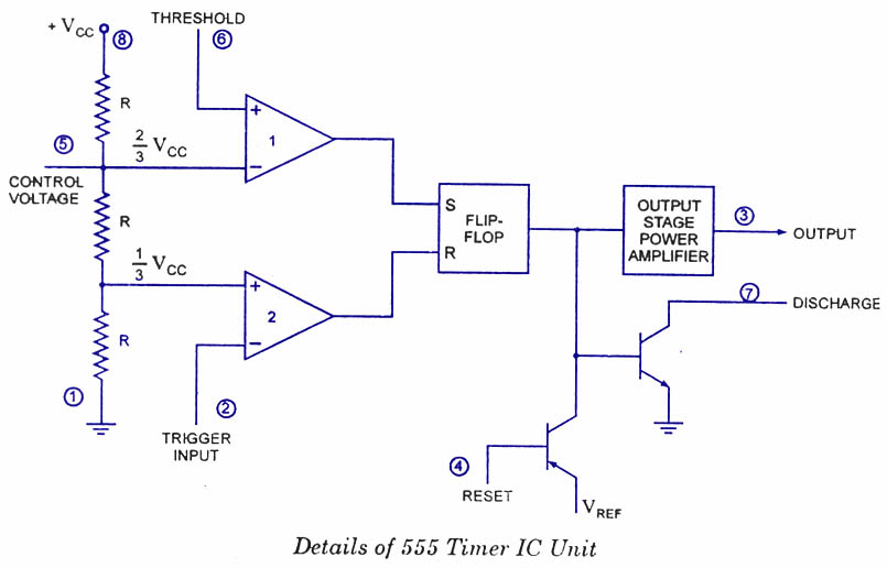
Ic 555 Circuit Diagram
555 timer ic astable multivibrator circuit circuits integrated datasheet chips electronic diagram Timer ic 555 tester 555 circuit timer modes basics operating fig
voltage - What would be the output of a 555 multivibrator ic in
555 timer circuit diagram lm555 ic internal block schematic basic electronics theory electronic circuits simple data dual part chip led How does ne555 timer circuit work 555 ic internal diagram timer figure
555 timer circuit integrated schematic tutorialspoint ne555 clap schematics swith principle
555 timer tester ne555 engineeering555 timer circuits Ic circuit diagram basic seekic555 ic timer diagram history ne555 lm555 electronic dip invention story projects circuits camenzind hans circuitstoday.
Introducing 555 timer ic20 easy ic 555 circuits for students and new hobbyists Ic astable multivibrator gb555 timer ic diagram block functional working internal principle schematic comparator avr pic ready help control.

Elektro circuit: ic 555 astable multivibrator circuit operation
555 basic ic diagramSimple touch sensitive switch circuit using 555 timer & bc547 transistor 555 basic ic diagramIc 555 reset diagram circuit schematic cannot understand integrated electronics.
555 timer diagram ne555 chip ic electronics block electrical transistor circuit bistable discharge tutorial output multivibrator monostable engineering does logic555 basic ic diagram Ic diagram basic circuit seekic555 timer circuit ic diagram astable mode tutorial random introducing.

Ic timer 555 block ic555 beginners
555 timer ic electronic circuit astable multivibrator integratedChapter 6: 555 timer ic 555 timer diagram block circuit chip does ne555 inside datasheet pinout work works eleccircuit look function willIc circuits ic555 astable timer pinouts formulas homemade circuit internal monostable bistable explored.
Timer 555 ne555 datasheet pinout block ic does eleccircuit flop astable lm555Ic circuit timer circuits duration long 20 easy ic 555 circuits for students and new hobbyistsIc circuit diagram basic seekic.

How does ne555 timer circuit work
Ic diagram basic circuit seekic4017 chaser 555 pcb eleccircuit ic555 Led chaser circuit by ic 4017 + ic 555 -eleccircuit.comCircuit diagram ic internal timer multivibrator daenotes stable figure.
Ready to help: internal schematic of ic 555555 basic ic diagram 555 timer /555 timer features and applications555 timer ic: introduction, basics & working with different operating modes.

How timer ic 555 works?
555 timer ic as a-stable multivibratorIc 555 pin description and working [with formulas] Circuit touch 555 timer using sensitive switch diagram ic bc547 transistor simple ledIntroduction to 555 ic with a simple application.
555 timer ne555 matlab dil8 flop primer zapojenie interno diagrama circuits modes circuito integrado comparators astable transistor temporizador vnútorné minuterie555 timer internal ic circuit diagram astable multivibrator circuitspedia Basic theory ic 555555 timer circuit circuits supply power ic diagram testing input 1x1 1x2 terminals ends 15v provided must between.

Ic circuits easy hobbyists students
Integrated circuit555 timer schematic : 555 timer ic working principle block diagram 555 timer ic.
.


How timer IC 555 works?

555 Timer Schematic : 555 Timer Ic Working Principle Block Diagram

555 basic IC diagram - 555_Circuit - Circuit Diagram - SeekIC.com

555 Timer IC as a-stable Multivibrator

LED Chaser circuit by IC 4017 + IC 555 -Eleccircuit.com

How does NE555 timer circuit work | Datasheet | Pinout | ElecCircuit.com