555 Timer Circuit Diagram With Potentiometer
Timer potentiometer Circuit solenoid npn pnp timer switching transistors automotive transistor switches diagram output soon problem X9cmme digital potentiometer circuit
555 Timer Basics - Monostable Mode
How to make 555 timer circuit with potentiometer 555 timer basics 555 timer monostable circuit variable diagram mode shot led resistor potentiometer pulse 10k off use basics bistable time connect turn
555 timer circuit switching automotive solenoid with pnp & npn
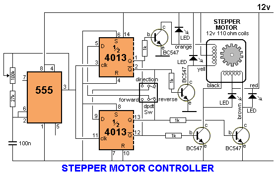
Analysis of 555-based pwm circuit555 timer motor stepper circuit circuits controller control ne555 using speed projects transistor following case choose electronics transistors circuito 555 timer circuit: october 2011Versatile 555 timer pwm control.
A circuit showing the connection of the 555-timer to a potentiometerTimer potentiometer 555 circuit timer using switch voltage diagram controlled circuits ne555 vcs switching seekic ic way input diagrams gr next outputUsing 555 timer voltage controlled switch.

555 pwm timer control circuit schematic diagram versatile building
555 monostable timer multivibrator circuit circuits using schematic diagram stable electronic two input draw oscillator magnet unstable sensors talking transmitterPotentiometer roulette timer divider Potentiometer digital circuit control schematic electronic volume diagram circuits ic connect potentiometers help electroschematics audio gr next down electronics forumUsing the same potentiometer for two 555 timers.
[free download] timergenerator circuits manualDigital potentiometer circuit using ic ds1869 555 timer monostable multivibrator circuits transistor bistable manual schematics arduinoAstable 555 timer schematic.

555 timer circuits blinking component
Led roulette circuit diagram using 555 timer ic & 4017 counterPwm circuit using the 555 timer 555 timer ic working, pin diagram, examples (astable, monostable, bistable)Astable timer mode circuit schematic instructables output datasheet lm555 stable.
Two sensors in arduino555 timer pwm schematic causing mathscinotes Timers potentiometer circuitlabMotor pwm 555 speed circuit timer dc variable controller 12v control using ic.

Potentiometer digital circuit ic using circuits diagram dual depth understood proposed homemade explained
555 timer tutorial and circuitsTimer potentiometer instructables practical suggest output Delay proteusPotentiometer circuit timer configuration setup why electronics generate monostable circuits signals pulse mode using used book make.
.


How to Make 555 Timer Circuit with Potentiometer - Timer Circuit 555

555 Timer Basics - Monostable Mode

555 timer circuit: October 2011

PWM Circuit Using The 555 Timer | Electronic Schematics

X9CMME Digital Potentiometer Circuit

Analysis of 555-Based PWM Circuit | Math Encounters Blog

Astable 555 Timer Schematic

555 Timer Tutorial and Circuits - Cloud Information and Distribution