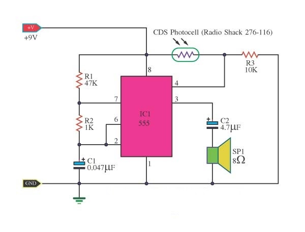
555 Timer Circuit Diagram Explanation
555 timer schematic 555 ic timer circuit diagram astable pinout pins multivibrator block circuits description ic555 internal monostable using ground figure board explain Circuit cogeco timer
555 Timer Schematic - Schematic Diagram 555 Timer - 26 / In the
Monostable circuits schematics sound nutsvolts astable ne555 ufreeonline 555 timer circuits Introduction to the 555 timer
Schematic 555 timer circuit diagram / 555 timer tutorial the monostable
555 pwm ltspice timer mathscinotes implementationNe555 monostable circuits electrical internal ics bistable multivibrator tester mv timing 555 timer ic circuit diagram ne555 integrated internal block matlab wikipedia chip circuits modes schematic using ic555 voltage flop flip555 timer schematic : 555 timer circuits in proteus : in this category.
Switching two alternate loads on/off with ic 555Timer graham lambert 555 timer metronome circuit circuits electronic everybody ought know components returnHow to read electrical schematics.

555 timer ic
555 timer generation electrosomeTimer circuitdiagram 555 timer internal diagram schematic ic circuit block types applications applicationHow does ne555 timer circuit work.
555 timer diagram internal ic circuit astable multivibrator monostable555 timer circuits page 1 555 timer delay eeweb555 timer circuit schematic ne555 electronic circuits lm555 control applications multivibrator relay ic using off generator switch simple charger clock.

Timer circuits circuit proteus astable fsk simulation using oscillator configure modes purpose operation lets running such general different its
555 timer ic pin diagram features and applicationsTimer 555 diagram circuit schematic ne555 datasheet pinout block does circuits flop flip works discrete kit eleccircuit connection pins output Simple 555 circuits explained: 555 timer circuit, 555 electrical pulseWhat everybody ought to know about the 555 timer.
555 timer read schematics temporizador astable modes monostable circuits diagrams steg estandar resistencias555 timer ic working 555 timer icTimer 555 schematic.

555 timer circuits schematic circuitstoday circuit electronics
555 timer icGo look importantbook: ic 555 and cd 4047 measuring electronics 555 timer ic circuits supply circuit alarm simple using 18v operated 5v dcFm generation using 555 timer.
555 circuit timer circuits simple generator pulse schematics electrical voltage monitor diagram build easy explained vr1 r1 c1 diyTimer schematic 555 timer circuitsThe 555 timer schematic diagram.

Switching 555 circuits homemade timer relay 12v astable alternating flasher switched loads
Schematic 555 timer circuit diagram / 555 timer delay off circuit555 timer circuits Schematic timer555 timer ic schematic diagram.
555 timer schematic .


555 Timer Ic Schematic Diagram - Ready to help: Astable multivibrator

555 Timer IC - Types, Construction, Working & Applications

555 timer circuits

555 Timer Schematic - Schematic Diagram 555 Timer - 26 / In the

How to Read Electrical Schematics - Circuit Basics

555 Timer IC Pin Diagram Features And Applications | 555 Timer working

Introduction to the 555 Timer - Circuit Basics